 Software
Gravity Correction
The gravity correction module in Horin Softwareis designed in accordance with industry standards.
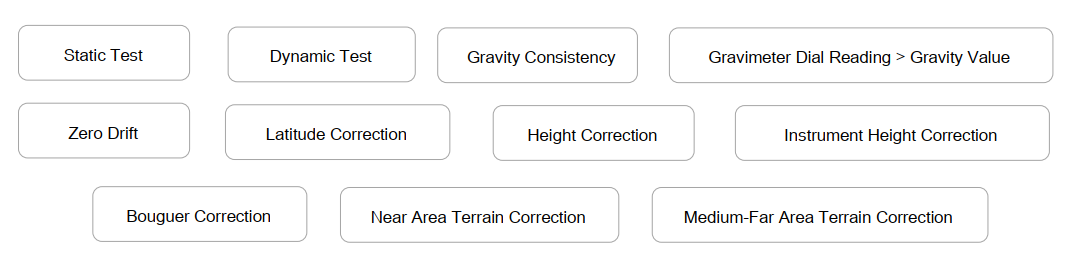
The conventional ground gravity correctioncontains 11 functions:
The marine gravity correction function is a professional module customized by Horin Company for marine prospecting.
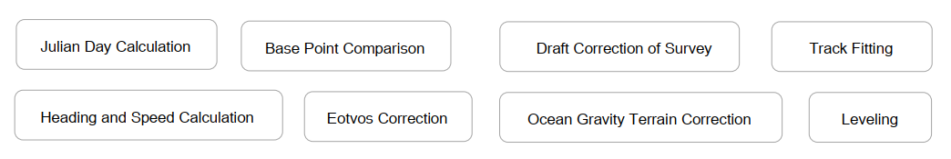
Ocean version adds 8 functions:
Gravity Correction
Julian Day Conversion (Pro)
Convert Julian dates of acquisition data to regular dates, or vice versa. For example, on January 23, 2016, this date converted to Julian is 2016023, which refers to the 23rd day of 2016. Julian dates cannot directly participate in functional calculations. You need to convert to conventional date formats by this tool before it participates in calculations.
Instrumental Determination
The determination of instruments in gravity survey, including the determination in dynamic, static and probe consistency of the instruments, all meet the standards for industry.

Base Point Comparison
Convert the relative gravity value to the absolute gravity value by the absolute gravity values of the base point. In order to reduce the accumulation of measurement errors, you need to perform the base point comparison before and after the survey.
Earth Tide Correction
The deformation of the earth under the gravity of the sun and the moon is called the earth's solid tide. For gravity survey, the gravity earth tide correction must be performed on the gravity observation data.
Reference formula: Reference specification SY / T 6957-2013 Technical Specifications for Marine Gravity Survey, page 8.
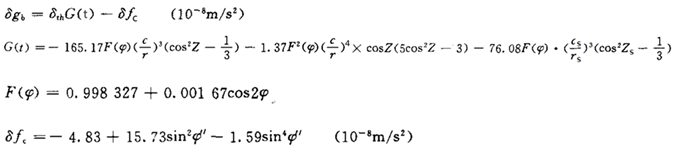
where:
δth——tidal factor, set as 1.16;
r——distance from the center of moon to the center of the earth;
c——average distance from the center of the moon to the center of the moon;
rs——distance from thecenter of the sun to the center of the earth;
cs——average distance from the center of the earthto the center of the sun;
Zs——Geocentric zenithdistance from the sun to the measuring point;
φ——latitude of the measuringpoint;
φ ′ —— latitude of the geocentricpoint of the measuring point.
Zero Drift
The zero drift of the instrument is a function of time. It only refers to the changes of readings due to fatigue of elastic components. Zero drift also known as pure zero point change, eliminating this change of reading is zero drift correction.
The zero drift algorithms in Horin Software refer to the specification "SY/ T 6957 – 2013" Technical Specifications for Marine Gravity Survey, page 9.
Reference formula:
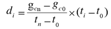
![]() ——The values of the late readings and early readings of base point corrected by the dial reading correction and the earth tide correction .
——The values of the late readings and early readings of base point corrected by the dial reading correction and the earth tide correction .
![]() ——reading time of late and early of base point.
——reading time of late and early of base point.
Draft Correction (Pro)
Draft correction belongs to the preprocessing of the ocean correction function.
Reference formula:
![]()
![]() —— draft correction value, the unit is mGal;
—— draft correction value, the unit is mGal;
![]() ——the average values of the heights of the left and right side of theship (near the gravimeter installation position) to the water surface before and after the survey, the unit is m. This value is obtained by inputting the measured value.
——the average values of the heights of the left and right side of theship (near the gravimeter installation position) to the water surface before and after the survey, the unit is m. This value is obtained by inputting the measured value.
![]() —— the time of comparing with the base point before the marine surveyand after the marine survey, the unit is h. This time is obtained by inputting the measured time.
—— the time of comparing with the base point before the marine surveyand after the marine survey, the unit is h. This time is obtained by inputting the measured time.
Draft correction belongs to the preprocessing of the ocean correction function.
Track Fitting (Pro)
The theory of the orthogonal polynomial fitting method is to make the difference between the coordinate of the measuring point and the coordinate of the fitting point for the entire surveyline meet the weighted least squares condition,obtain the orthogonal polynomial coefficient and reduce it to the equivalent power polynomial form. The power polynomialis used to express the coordinates of the track line as a function of time t. In this way, the coordinates of the line corresponding to that time can be obtained from any time within the range of the line.
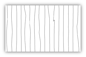
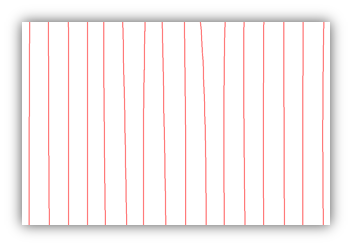
Before track fitting After track fitting
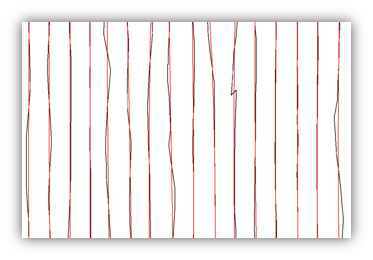
Contrast effect
Eotvos Correction (Pro)
The error caused by the relative movement between the survey carrier and the earth is called the eotvos error. The method to eliminate the eotvos error is the eotvos correction. eotvos correction accuracy is mainly determined by the positioning accuracy and the heading and speed accuracy of the survey vessel. In marine gravity surveys, eotvos correction has been the main source of error that affects survey accuracy. This function was optimized from the following three aspects: track fitting, reasonable heading and speed calculation. This improves the accuracy of the correction overall.
Reference formula: Algorithm Reference Specification SY/T 6957 – 2013Technical specifications for marine gravity survey Page 9
δge = 7.499 × V × sinaA × cosφ + 0.004V2
A——True azimuth (°) of track; V——Speed (m / h); φ——Geographical latitude (°) of survey point.
Or:
δge = 7.50 x [(λ′-λ) ÷ (t′-t)] xcos2φ
λ ′ and λ — longitude (°) of the two points adjacent to the current survey points; t ′ and t — corresponding observation time (s) of above two adjacent points;
φ — latitude (°) of the survey points.
Calculation of Normal Gravity field
Elimination of the change in gravity field caused by the latitude difference between the measurement point and the basepoint,also called normal gravity correction.
Reference Formula: Reference Specification SY/T 6957 – 2013 Technical Specification for Marine Gravity Survey Page 10
Helmert formula: r = 978.030 (1.0 + 0.005302Sin2B-0.000007Sin22B)
Cassini formula: r = 978.049 (1.0 + 0.005288Sin2B-0.0000059Sin22B)
Formula of International Union of Geodesy and Geophysics: r = 978.0327 (1.0 + 0.00530244Sin2B-0.00000585Sin22B)
B ---- Latitude.
Bouguer Correction
Bouguer correction remove the gravity influence of the rock strata between the observation point and the geoid.
Bouguer correction generally consists of two parts: the middle layer (the imaginary infinite parallel rock layer between the observation point and the geoid) and the local terrain correction.
Reference formula: Reference specification DZ/T 0171-1997 Specification for large-scale gravity surveys, page 19.
δgB =[0.3086(1+0.0007cos2φ)-0.72×10⁻⁷H- 0.0419ρ×10-3(1+![]() )-
)-![]() )]×△H
)]×△H
φ ——latitude of the survey point; H——altitude elevation, m; △ H —— the height difference of the survey point relative to the total base point, m;
ρ —— density of the middle layer, kg / m3; R—— correction radius of the middle layer, set as 20km.
Terrain Correction (including Marine Terrain Correction,Pro)
The terrain correction base on a standard plane of the measurement point, eliminating the gravitational influence of the strata materials around the measurement point that is higher or lower than the planeon which the measurement point is located. After correction, the measurement point can be regarded as being on an infinite plane, no strata materials above it and completely filled strata materials under it. Gravity terrain correction can be divided into two parts: "near-area correction" and "medium-far area correction".
Reference formulas: "Specifications for Large-Scale Gravity Surveys DZ/T0171-1997", "Specifications for Regional Gravity Surveys DZ/T0082-93", and "SY/ T 6957-2013 Technical Regulations for Marine Gravity Survey".
Three types of near-area terrain correction:
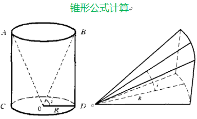
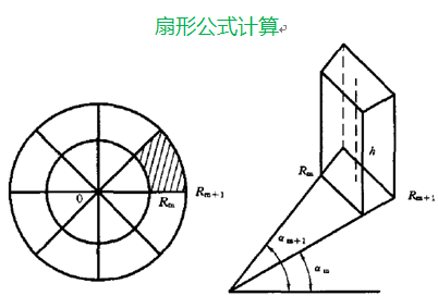
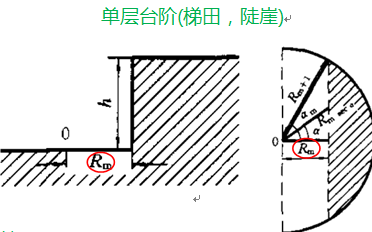
Cone (within 0-10m) Sector shape (within 10-20m) Simple steps (such as bench terraces and dams,similar to steps)
Two types of medium-far area terrain correction: far area terrain correction requires high-precision terrain data.
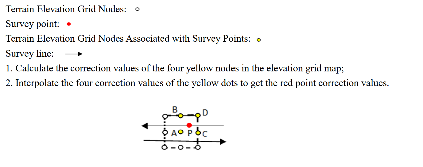
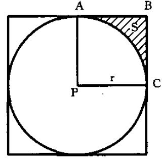
Square domain calculation method Schematic diagram of circle field
版权所有:北京金浩林勘探技术有限公司 京ICP备12050676号
公司地址:北京市海淀区苏州街49号院7号楼610/616室 联系电话:010-62611285 服务投诉电话:13521903951 传 真:010-62611285 公司邮箱:sale@horinexplore.com
 Current Position:
  客服
客服